
Superprojected, Semiprojected and Subprojected Geodesics
David Anderson
Originally written in May 1999
One of the reasons I like mathematics is that you can look at something for a long time, examining it from many different perspectives, but then suddenly slip around and look from the side to notice something new and bizarre!
Geodesics have been boiled down to mathematics in my papers - and now I have snuck around to one side to change my point of view...
My take on geodesics has been to use a single equilateral side of either the icosahedron, octahedron, or tetrahedron, tesselate it with a triangular mesh, and project the mesh vertices onto its circumscribing sphere.
To this point, all of the work I've done has centered around the development and use of this of projection mechanism, and then determining lengths and angles from the results.
But like Euclid's geometric postulates, if one part of the foundation gets modified then an entirely new take on the successive work can arise leading to bizarre new forms.
I decided to reformulate the geodesic patch shells as a family of parameterized surfaces.
The parameters describing the platonic solid, geodesic frequency, and edge length had all already been made part of the calculations - but not the parameters that control the projection.
I've talked about quantifying the bulge of a geodesic projection before - the closer the point being projected is to the center of the underlying solid the farther it has to be projected to reach the circumscribing sphere.
The distance a point needs to be projected is
where d is the projected radial distance, rs is the radius of the circumscribing sphere, and ro is the original, unprojected radial distance.
The radial distances are found in spherical coordinates - the projected radial distance is the difference between the projected and unprojected distances.
When we put it in these terms, we can create a parameter p that indicates the "state" of the projection:
When the value of p is 0, the patch is unprojected, r = ro.
When the value of p is 1, the patch is projected onto it's circumscribing sphere, r = rs.
We are immediately given to consider what we get when the value of p is not 0 or 1.
It is easy to imagine what this must be like:
-
When p is between 0 and 1, the surface is in an intermediate state between the polyhedron and the sphere; as the parameter varies from 0 to 1, the flat-faced solid inflates to become the sphere.
The geodesic is semiprojected.
-
When p is greater than 1, the surface puffs out - the projected distance is exagerated.
The higher the value of the parameter, the more the bulging.
The geodesic is superprojected.
-
When p is less than 0, the surface puckers.
The centers of the sides draw in until they reach the critical point where p is equal to -ro/d.
When this happens the side touches the solid's origin. The geodesic is subprojected.
-
When p is less than -ro/d, the geodesic is degenerate, it's sides passing through each other.
These parametric-projected geodesics make up a continuous family of mathematical forms, and are a lot of fun to build!
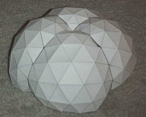
The following pictures are paper models of 7-frequency octahedral "hemispheres", made up of four patches.
The actual patch patterns are available by clicking each picture.
If you'd like to make your own, just make four copies, cut them out, and tape them together, as you did in Constructing Geodesic Patch Surfaces, Part III.
If you want to construct a "sphere", make eight copies.
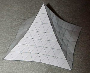 |
subprojected
projection parameter = -0.3
The surface puckers.
|
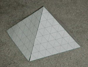 |
unprojected
projection parameter = 0.0
The original platonic solid.
|
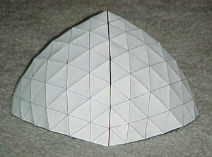 |
semiprojected
projection parameter = 0.5
Inflating to the geodesic.
|
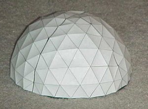 |
projected
projection parameter = 1.0
The traditional projection onto the circumscribing sphere.
|
 |
superprojected
projection parameter = 2.0
The surface bulges.
|
The remaining consideration I have is to figure the effect of the parameterization on the warped octet truss.
The trick comes down to recalculating the "stretch factor" - the scalar of the distance above or below the warped plane of geodesics.
The new stretch factor s becomes
The new stretch factor maintains the tetrahedral strength of the warped octet truss as the bulge factor changes.
The following table contains links to VRML worlds featuring 5-frequency octahedral geodesic patches with internal and external warped octet trusses.
By clicking a link you will be put into VRML, where the 3D models may be manipulated.
Although the parameterized geodesics are not necessarily anything special, certainly not in the sense that Fuller developed the spherical geodesic structures, they do have some particular charm.
By evolving a continuous progression of surfaces, an interesting perspective on the projective mathematics has become apparent - and a new set of buildable structures with interesting characteristic for geodesicists to examine is now available.
Just the sort of thing that keeps me exploring all this stuff.
Looking back over the code I'd previously written, I got it right for the geodesic layer, but wrong for the truss layer.
After a few hours of hacking, I think I've remedied this situation.
The way it used to work was to create a patch with a standard octet truss above or below it and project each from the geodesic origin.
However, this caused distortions of the truss layer - to the point that it was no longer even close to what would be considered a truss: the tetrahedrons were too severely skewed and misshapen.
The new code in this paper instead attacks the problem from the mesh genertation onward.
Now, the geodesic and truss mesh are first generated on the same plane in the patch; then during projection each is projected differently:
The geodesic layer is pushed outward to the sphere by changing each hub's radius coordinate to the original radius plus the additional radial part multiplied by the projection factor.
The truss layer is pushed outward, but in a more complex way.
Like the geodesic layer, it is also pushed to the sphere taking the projection factor into account.
But then for each truss hub, the the plane made up of the directly connected hubs in the geodesic layer is found.
The unit normal to that plane is scaled and added to the position of the truss hub so that the octet truss is always 'locally' unskewed relative to each subface.
The scaling of the normal is the key to warping the truss: it varies directly with the radius of the sphere, inversely with the frequency of the tesselation, and directly with the height of the tetrahedron.
Finally the normal is multiplied by the by the fraction of the radial change, and added to the truss hub's position.
After adjusting this, I looked at the results in VRML, and it still didn't look right.
Icosahedral patch truss tetrahedrons were too tall and tetrahedral path truss tetrahedrons weren't tall enough, while octahedral patch truss tetrahedrons were about right.
It didn't make sense.
It was time for some head-scratching.
In the icosahedral case, the altitude of tetrahedrons in the truss needed to be reduced.
In the tetrahedral case, they needed to be increased.
What was different about these two patches?
Nothing is different about the way the projective mathematics is done - what is different is the context of the geodesic patch!
The equilateral triangle each patch is formed from is positioned differently relative to the origin for each polyhedron. Thus,
A tetrahedral patch has to cover a quarter of a sphere,
An octahedral patch has to cover an eighth of a sphere, and
An icosahedral patch has to cover a twentieth of a sphere.
Assembling a table of relative factors (4, 8 and 20) I used these to reduce the altitudes of the tetrahedrons in the octet truss proportionally - and the results were clean!
Now the tetrahedrons in the warped octet truss were as close to appropriately sized tetrahedrons as possible, discounting the effects of bulging of the geodesic projection.
The new code builds better trussed patches than the old!
I'm only sorry that I hadn't noticed the problem fourteen years ago.
But, better late than never.


