
David Anderson
Originally written in June 1999
As soon as I parameterized the projection of the geodesic patch and created my first puckered and puffy domes, as described in Superprojected, Semiprojected and Subprojected Geodesics, I was struck with the thought of building a dome out of differently-projected geodesic patches. Some interesting structures could be created: some parts bulging, some parts dimpling, some almost flat, and some spherical - the possibilities were tremendous. Of course there were likely to be mechanical considerations, but these were certainly worth fighting through! That's what these efforts are all about.
The big problem with the parameterization is that the edges of differently projected patches do not have the same curvature. The edge needs to be the same for all patches (which are generated with the same platonic solid, frequency and unprojected edge length) or else they won't connect together without a seam. For different values of the parameter p, the edges are differently shaped:
| p < 0 | subprojected | the edge dimples |
| p = 0 | unprojected | the edge is flat |
| 0 < p < 1 | semiprojected | the edge is rounded |
| p = 1 | projected | the edge is circular |
| p > 1 | superprojected | the edge bulges |
Unless the values of p are the same, the edges will be mismatched. Only the corners of a patch are coincident; to connect the mismatched edges, a series of struts would have to be used between the edge vertices of adjacent patches. This just won't do at all - we dont want connecting stuts on the geodesic shell.
The first step must be to reformulate the edges. In order to keep the edges the same, the parameterization must leave them alone. The rest of the projection should blend into the edge smoothly, not abruptly - some function needs to be found which can be used to bias the projection.
 A straightforward solution presents itself. If we use the perpendicular distance from a vertex to an edge, then the distance function works as a nice, linear multiplier.
Since we have three edges of a patch, we have three distances functions.
We will use their normalized product as the blending function:
A straightforward solution presents itself. If we use the perpendicular distance from a vertex to an edge, then the distance function works as a nice, linear multiplier.
Since we have three edges of a patch, we have three distances functions.
We will use their normalized product as the blending function:
f v = d a d b d c / N
For each vertex in the geodesic mesh, the blending function produces a value that can be used to scale the projection - scaled so that the vertices on the edges of the patch are not adjusted but the patch's internal vertices are scaled in proportion to their normalized distance from the edges. The value of N normalizes the values of the blending functions to be between 0 and 1.
This blending function keeps the shape of the edge the same as it starts from; in the case of our projections from platonic solids, the edges are unprojected and straight. I decided that I'd like to use something different. Since I like geodesics, I thought a circular edge was appropriate. So, before applying the blending function with the projection parameter, I decided to pre-project the platonic vertices onto the geodesic sphere. By doing this, the our projection changes; we can call it the PFG projection, for Parameter From Geodesic. The new projection has a different, simpler nomenclature than our original one:
| p < 0 | subprojected | the edge is circular | the surface dimples |
| p = 0 | projected | the edge is circular | the surface is spherical |
| p > 0 | superprojected | the edge is circular | the surface bulges |
There is no longer a semiprojected type; the geodesic becomes the single, special basis for the PFG projection.
It is a simple matter to adjust the software to use the PFG projection. The projected distance is set equal to the circumscribed sphere's radius plus the product of the projection parameter, the distance between the platonic solid and the geodesic at that vertex, and the blending function at that vertex. Because the value of the blending function along the edge is 0, the projected edges will lie on the geodesic.
In transfering the designs to paper shells, we find that the superprojected geodesics follow the same sweetest pattern we determined previously. I laid it out according to the templates which were developed in Constructing Geodesic Patch Surfaces, Part I and had no problem at all. However, when I tried laying out the subprojected patches I ran into a problem - saddle points!
On a concave or convex surface, the plane which is normal to a point lies completely on one side of the the surface: the surface curves away in the same manner around the point. When a surface is concave along one direction at a point, and convex in another, the normal plane divides the surface. If you imagine orienting yourself to straddle this point, both legs ride the surface down, while the surface bends up ahead and behind you - just like a saddle.
Saddle points have an interesting consequence when making geodesic paper models. The angles around regular concave or convex points always total less then 360o in a geodesic because a wedge needs to be removed to lift it up or sink it below the 2D template plane when it is folded and the gap is closed. When the vertex is near a saddle point, the angles around it can total more than 360o. Unless the vertex is bisected, not just opened by a wedge, the flattened pattern cannot be drawn on a flat sheet - you can't fit more than 360o of angles around a point on a plane.
So, this all means you have to design the template in a much more ad hoc way. Instead of a simple pattern, you have to work around the saddle points. In some cases, it may even be necessary to divide a pattern into several pieces and join the resulting subsurfaces.
In order to test joining the patches, I decided to do a little building. I created a few octahedral patch templates.
I decided to go back to the 7 frequency patches and designed one with a parameter of 2.0, and another with a parameter of -1.0. The first patch bulges out significantly; the second patch dimples in. I made four of each and alternated them around the octahedron.
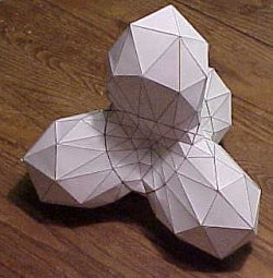
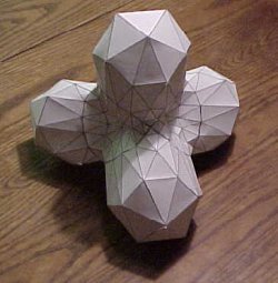
An interesting shape... a tetrahedrally-lobed octahedral geodesic.
Since the edges all join precisely, any projection will work and can be used to create domes with a variety of shaped patches. Although they don't look traditional, they are certainly fun to build, and add a new dimension of geodesically-derived shapes.