 , the tetrahedral patch covers
  , the octahedral patch covers
  , and the icosahedral patch covers
  .
.

David Anderson
Originally written in March 1999
How can the waste of a geodesic covering be calculated? That question has a straightforward answer and the calculations are not too difficult. And the identfication and derivation of some characteristic constants for the platonic solids make it all very interesting.
When we are going to manufacture a geodesic covering from a template, waste is everything we cut away and don't need. Waste has a special status from the Fullerean geodesic perspective - minimum waste is important since it represents the natural state; nature tries to minimize energy expenditure and material usage - it gets the most out of the least. This idea has a lot of appeal and seems like a reasonable goal for our efforts.
By using this waste-is-unused-material definition, the calculation of waste may be made directly: the waste of a geodesic patch covering when cut from a single sheet is equal to the fraction of the flattened surface area of the sphere the patch covers minus the total area of the subfaces of the patch. The calculation for each type of geodesic patch may be approached the same way - it does not matter whether the patch is tetrahedral, octahedral, or icosahedral; the waste always equals the flattened spherical surface fraction minus the total subface area.
In our derivation we will use either the shortest or sweetest configurations from Part I. The number of cuts to an internal vertex along subface edges is minimum in these configurations, and the line between a corner and a center is uninterrupted. These characteristics insure that the average schematic length of a path to an internal vertex is minimized. Other cutting schemes which have this property may be used; they will have the same minimal average schematic path length. Without this sort of requirement, the convex hull of the schematic patch could grow unbounded as frequency increases.
Before we descend deeper into the wasteland, we will get geodesic surface area convergence out of the way.
It seems reasonable that as the frequency of a geodesic patch increases, there is a limit to its surface area - otherwise as the frequency increased it would cover an infinite region. The limit is the corresponding fraction of the surface area of the circumscribed sphere which the patch approaches. As the geodesic subfaces are successively divided into smaller and smaller triangles the projection more and more closely approaches the surface of the circumscribing sphere, and the difference between the sphere's surface area and the surface area of the geodesic will decrease. At the limit, when the geodesic frequency becomes infinite, the difference will vanish.
One of the conveniences of working with a patch is that the basic projection mathematics is the same for each equilaterally-faced platonic solid; only the fraction of coverage of the circumscribing sphere is different.
It takes four patches to cover a sphere tetrahedrally, eight octahedrally, and twenty icosahedrally.
Since the surface area of a sphere is  , the tetrahedral patch covers
  , the octahedral patch covers
  , and the icosahedral patch covers
  .
.
To show the convergence of the geodesic to the ideal, this table illustrates how increasing the frequency of the geodesic patch brings the surface area closer to the theoretical limit.
We set the radius  of the solid equal to one to make the results easier to see:
| Surface Area Covergence for Geodesic Patches with respect to Frequency | |||||||||
| Geodesic Frequency |
Tetrahedral Patch Area | Octahedral Patch Area | Icosahedral Patch Area | ||||||
| 1 | 1.15471 | 36.756 % | 0.86602 | 55.133 % | 0.47873 | 76.192 % | |||
| 2 | 2.11258 | 67.246 % | 1.30221 | 82.902 % | 0.58329 | 92.833 % | |||
| 3 | 2.60632 | 82.962 % | 1.44066 | 91.716 % | 0.60753 | 96.691 % | |||
| 4 | 2.76482 | 88.007 % | 1.49332 | 95.068 % | 0.61645 | 98.111 % | |||
| 5 | 2.88451 | 91.817 % | 1.52008 | 96.772 % | 0.62027 | 98.719 % | |||
| 6 | 2.95679 | 94.118 % | 1.53513 | 97.729 % | 0.62299 | 99.152 % | |||
| 7 | 3.00137 | 95.537 % | 1.54439 | 98.319 % | 0.62439 | 99.375 % | |||
| 8 | 3.03247 | 96.527 % | 1.55047 | 98.706 % | 0.62531 | 99.521 % | |||
| 9 | 3.05430 | 97.221 % | 1.55468 | 98.974 % | 0.62594 | 99.621 % | |||
| 10 | 3.07023 | 97.729 % | 1.55771 | 99.167 % | 0.62639 | 99.693 % | |||
| 20 | 3.12322 | 99.415 % | 1.56749 | 99.790 % | 0.62783 | 99.922 % | |||
| 50 | 3.13865 | 99.906 % | 1.57026 | 99.966 % | 0.62824 | 99.987 % | |||
| 100 | 3.14088 | 99.977 % | 1.57066 | 99.992 % | 0.63830 | 99.996 % | |||
 |
3.14159 | 100 % | 1.57079 | 100 % | 0.62832 | 100 % | |||
It is interesting to note the rate of convergence. Though all the surfaces converge as the frequency increases, they converge at different rates. The icosahedron starts out closer to the shape of a sphere than either the tetrahedron or octahedron, and by the time the frequency is six, the surface area is within 1% of the maximum surface area. However, this statistic must be tempered with the observation that the same frequency icosahedral geodesic sphere contains 2.5 times more subfaces than an octahedral geodesic sphere, and 5 times more subfaces than a tetrahedral geodesic sphere.
The calculation of waste is centered around flattening a geodesic patch by making cuts to each internal vertex. We end up with a template which can be used to create many patches. Patches are cut from pieces of the desired material, folded, and then attached along the cuts. The material which is cut away is the waste we wish to minimize.
What we are searching for is the theoretical minimum-waste boundary for the template designs which we determined were the most efficient. As we saw in the convergence table, the surface area of a geodesic shell converges to a given value for a dome of a given radius. We are able to flatten a spherical section by modeling it with an infinite-frequency geodesic patch cut according to our template strategy. Since this infinite-frequency geodesic section has the greatest possible surface area, its flattening should define the minimum hull which contains all the lower-frequency flattened geodesics and from which the minimum waste may be calculated.
But how do we flatten an infinite-frequency geodesic patch?
The answer is, of course, not by doing it in any finite way. Since we know the efficient-template strategy keeps the distance between the edge and center of a geodesic patch at a minimum by cutting the shortest distance from the edge of the patch to each internal vertex, we can determine the boundary analytically as a geodesic projection.
 What we need to do is determine the boundary of the flattened spherical secion.
Once we have this, we can determine the area contained in this hull.
Then we can combine it with the area of the geodesic at various frequencies - the waste is the difference between this minimum flattened area and the surface area of the geodesic.
The boundary can be formulated as the distance from the center of the spherical section to its edge in each direction along the surface of the sphere. We will end up with 360 degrees of distances around the center which define the boundary we may use to determine area of the flattened region.
We start with an equilateral triangle  ABC which has been projected onto the circumscribing sphere.
This becomes an equilateral spherical section corresponding to the projected geodesic patch (either a quarter of a tetrahedron, an eighth of an octahedron, or a twentieth of an icosahedron.)
The side of the platonic solid being projected has corner points A, B, and C, and a point at its center D.
We make the point E on the surface of the sphere the projection of D.
E is the center of the spherical section from which we will measure the distance to the boundary's edge.
The center of the solid itself is O.
The lines OA, OB, OC, and OE, are all the same length, the radius
  of the sphere.
Again, it is not important which solid we use as a base - each of the tetrahedron, octahedron, and icosahedron use the same mesh and the same projective geometery; the only difference in our calculations is the length of the edge for a solid of a given diameter.
| Edge Length Scaling Factor | |||
| Platonic Solid | Radius Multiplier s | Numeric Value | |
| Tetrahedron |  |
1.632993 | |
| Octahedron |  |
1.414214 | |
| Icosahedron |  |
1.051462 | |
The boundary thus becomes the projected boundary of the underlying equilateral triangular side of the platonic solid.
Since the projection is onto a sphere, the shortest path between two points along the sphere's surface is a part of a great circle - the length of the path is the 
 , where
  is the angle subtended by the arc between the points.
 Of course,
  will vary depending on the angle
  which aligns the great circle in the direction we wish to measure.
Therefore
  is a function of
  , and we must work through
  to get the boundary.
To find the edges of boundary to project, we take a look at  ABC.
We need to let
  range completely around the center to obtain the entire boundary.
By conecting the corners A, B, and C to the center D, and knowing that
  ABC is equilateral, we find we now have three symmetric triangular regions,
  ADB,
ADB,  BDC,
BDC,  CDA.
Each of these regions is also symmetric; subdividing
  BDC, for instance, gives us the symmetric triangles
  BDF and
  CDF, where F is the midpoint of BC.
 This substantially reduces the work we need to do to find our answer - we only need to find the area on the sphere corresponding to one of the symmetric areas, say
  CDF and multiply it by six -
  need only range over sixty degrees.
And since
  CDF is a 30-60-90 triangle, and we know the length of CF is half the length of a side of
  ABC,
ABC,  , then we know the length of DC is
  and the length of DF is
  .
.
Now things begin to get interesting.
As we swing  from 0 to 60 degrees, the length
  of the CF-intercept from D varies.
If we strategically position D at (0,0), then the CF-intercept is at (
 ,
,  ).
The value of
  is the distance from D to the CF-interception point:

The key to all this is the value  , the length of the CF-intercept, because we need this to calculate
  for
for  values in the range of 0o to 60o.
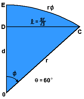 We also need to find d, the distance from the center of the solid O to the center of the equilateral side
  ABC we are projecting.
Once we know d, we can find
  as
as  .
.
We find d by considering  at 60o.
In this situation, the CF-intercept is coincident with the line DC, the length of the CF-intercept
  is
is  , and the distance OC is the radius
  of the underlying solid. Knowing this we can calculate d simply from the Pythagorean theorem.

It is good to see that  pops out of the equation so nicely, since when we combine it with
  to calculate the arctangent,
  needs to cancel out - the angle
  is independent of the radius of the solid, of course!
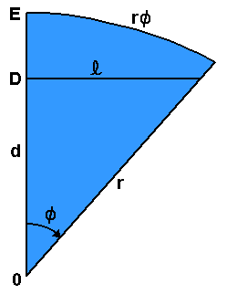 Now we know
  and d, and thus we know
  for any
  between 0o and 60o.
Whew!
We shall take it just a little further,

and with a little judicious simplification end up with

If we let  , then k is a characteristic constant for each solid, and

A simple result, indeed! For each of our solids, then
| Sphere Coverage Scaling Factor | |||
| Platonic Solid | Characteristic k | Numeric Value | |
| Tetrahedron |  |
1.414214 | |
| Octahedron | 1/ |
0.707107 | |
| Icosahedron |  |
0.381966 | |
So, now we know the analytic form of the flattened boundary b for a symmetric sixth of the spherical section:

where  ranges from 0o to 60o.
At this point we can take a look at the boundaries. We plot b from 0o to 60o:
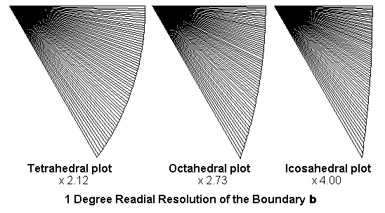
By flipping these boundaries and rotating them to get 360o worth:
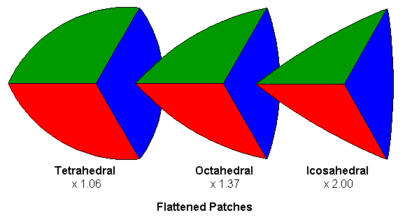
The red, green and blue areas indicate the symmetric portions of the plot which correspond to the symmetric portions of our templates in the previous paper.
Some interesting properties about these curves are apparent when you look at them - the flattened tetrahedral boundary bulges more than the octahedral, which in turn bulges more than the icosahedral. Thinking about it, we'd expect this. Since the tetrahedral patch has to "wrap" more of the sphere (twice as much as an octahedral path, and five times as much as an icosahedral patch) it should have to be distorted more.
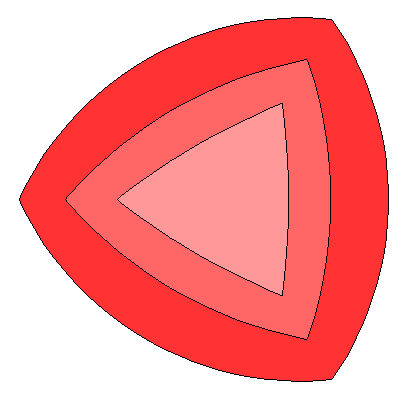 Also notice the scale factors; these diagrams have all been normalized so that the distance between the corners is the same for each boundary.
If we superimpose the boundaries without normalizing, we can see that for platonic solids with the same radius, the flattened icosahedral patch is smaller than the octahedral patch, which in turn is smaller than the tetrahedral patch.
Looking at these superimposed patches you can see that they form a progression - the bulge is purely dependent on the characteristic value k.
It leads one to consider whether or not there are hidden geodesics that would correspond to other k values.
But what platonic solids might these correspond to?
Perhaps complex ones which lie in complex space - or maybe even a fractal geodesic space, where an integral number of faces is not required.
Hmmm...
That may become the basis for some further study.
To find the area a of the boundary b, we merely need to solve a radial integral and multiply by six:

Now, the unsatisfying part of this is that there is no known closed-form analytic solution of this integral. I tried for a while, then I went to integrals.com, then I sent some mail to the folks at Wolfram, the makers of Mathematica. No luck anywhere. So we have this wonderful integral which I would love to have a nice simple solution for, but will admit none. Rats. It seems we are stuck using numerical integration to get a non-exact numeric answer.
Of course, 'stuck' is a relative term. Using our friend, the programmable electronic digital computer, we can do numerical integration to calculate the result pretty closely. Close enough for me, anyway. The following results are calculated from the sum of 6000 hundreth-degree triangles from 0o to 60o with a radius of one.
| Numeric Integration of Boundary Areas | ||||||
| Platonic Solid | Flattened 60o Area |
Flattened Boundary Area |
Flattened Sphere Area |
|||
| Tetrahedron | 0.57564 | x 6 | 3.45383 | x 4 | 13.81532 | |
| Octahedron | 0.27449 | x 6 | 1.64693 | x 8 | 13.17544 | |
| Icosahedron | 0.10678 | x 6 | 0.64066 | x 20 | 12.81323 | |
These values are very close to those we would calculate if we knew a closed form solution of the integral - the results above were calculated at various angular resolutions to make sure there was convergence.
Given these values, we finally know what we need to know to calculate the waste!
| Waste: the Difference between the Boundary Areas and the Infinite-Frequency Geodesic | ||||||||
| Platonic Solid | Flattened 60o Area |
Flattened Boundary Area |
Percent Waste |
|||||
| Tetrahedron | 0.05204 | x 6 | 0.31225 | 9.04 | ||||
| Octahedron | 0.01269 | x 6 | 0.07614 | 4.62 | ||||
| Icosahedron | 0.00206 | x 6 | 0.01236 | 1.93 | ||||
The waste values in this table are the minimums, since frequencies lower than infinity do not as closely approach a sphere, and the overall waste will be greater. We also see that in terms of waste, the icosahedral geodesics are the most efficient it terms of coverings. A covering made of patches which are cut from our icosahedral template will have a theoretical minimum waste of less than two percent - a very efficient use of materials!
We can see that although we are not going to be creating infinite frequency geodesics, we can use the results with our convergence data to calculate waste values for lower frequency geodesics. The important point is that we can predict our use of materials and the waste of the most efficient patch templates - and also that if we manufacture our geodesic skins from flat sheets, there must be waste!
So it seems we have it!
We can now proceed comfortably to making our geodesic coverings. We know that our designs will scale with the radius of the geodesic, and that the area of the covering will increase as the square of the radius. Our intention will be to create scalable geodesic patch templates so that we can have some fun making geodesic domes and balls.